Post-Conference Technical Excursions
Delegates of EGCON 2025 have a unique opportunity to embark on a three-day post-conference technical excursion to one of two remarkable hydroelectric projects, each offering distinct engineering geological insights and cultural experiences.
Those visiting the iconic Tehri Dam will witness the marvels of Himalayan hydro-engineering firsthand, complemented by visits to the sacred cities of Haridwar and Rishikesh. Meanwhile, delegates exploring the Gandhi Sagar Pumped Storage Project will gain insight into the complexities of constructing a pumped storage system in the stable cratonic region of peninsular India while experiencing the rich historical and architectural heritage of Rajasthan, including its forts, palaces, and vibrant cultural traditions.
These excursions promise a holistic experience—enhancing understanding of hydro-engineering across diverse geological settings while immersing delegates in India’s rich cultural and historical heritage.
2400 MW Tehri Dam Complex
Excursion Itinerary
Excursion Start Point: Dehradun
Day/Time |
Engagement |
Day.1/ 08:30 |
Dehradun Airport/ Rail Station Pick-up/ Breakfast |
Day.2/ 08:30 |
Breakfast |
Day.3/ 08:30 |
Breakfast |
Notes:
Delhi-Dehradun-Delhi travel: Delegate is requested to arrange through Event Managers (Alpcord) or a travel agent of their choice.
INR 20000+GST per person
Inclusions:- Hotel accommodations (Tehri, 2 nights)
- Breakfast, lunch, and dinner as per itinerary
- Guided sightseeing tours in Rishikesh and Haridwar
- Technical visit to Tehri Dam
- Entry fees and permits, unless specified otherwise
- Transfers as mentioned in the itinerary
Exclusions:
- Delhi-Dehradun-Delhi airfare/ train tickets
- Alcoholic beverages
- Tips and gratuities
- Activities not listed in the itinerary

|

|

|
||
| A cornerstone of India’s renewable energy infrastructure and a remarkable feat of hydro-engineering, the 2400 MW Tehri Hydropower Complex integrates multiple components for power generation, water storage, water supply for irrigation and potable use. The project caters for about 270 million gallons per day of drinking water for Delhi and parts of U.P. It has provided additional irrigation facility for about 2,70, 000 hectares of land and also has stabilised the existing irrigation facilities for more than 6,00,000 hectares of land. With a reservoir capacity of 3.54 billion cubic meters, the 260.5 m high rockfill Tehri Dam—one of the tallest in the world, constitutes the primary component and has a generating capacity of 2000 MW power of which 1000 MW is from pumped storage arrangement. Complementing this, the Koteshwar Dam, a 97.5 m high concrete gravity structure, stores water released from Tehri, provides 35 million cubic meters of pondage for pumped storage generation, and contributes additional 400 MW to the total output. A defining feature of Tehri dam spillways is that they have been designed for a probable maximum flood of 15540 cumecs (inflow) while the routed flood discharge corresponding to maximum water level (MWL) of 835.0m through the spillways would be of the order of 13400 cumec. The designed discharge capacity of the gated chute spillway, located on the right bank is 5380 cumec while the hallmark feature of the two 12m diameter right bank shaft spillways is the Morning Glory which is a specialized eye-catching engineering design with a combined discharge capacity of 3800 cumec and it brings an exquisite specter while discharging the excess water from the reservoir. A very unique feature on the right bank spillways is the 8.5 m diameter intermediate level outlet (ILO) tunnel which is located 40m below the dead storage level to serve a specific purpose of maintaining an uninterrupted supply of water of holy river Bhagirathi for the downstream areas. The Tehri Dam Complex is located in the Main Himalayan Belt, within the Lesser Himalaya, bounded by major tectonic structures - the Main Central Thrust to the north and the Main Boundary Fault to the south. About 5 km NNE from the dam site, the Srinagar Thrust represents a significant geological feature in the region. The project area primarily consists of folded Chandpur phyllites, characterized by varying proportions of argillaceous and arenaceous constituents. Extensive subsurface investigations, including drilling (207 nos), exploratory drifts (5 nos.), and an under-river drift, were undertaken to develop a comprehensive engineering geological model, guiding the complex design and construction of the project. Given the high seismicity of the region (seismic zone IV), early-stage planning faced significant local concerns regarding potential risks to the dam. These were systematically addressed through rigorous engineering design and an extensive instrumentation network embedded within various structural components to monitor the dam's integrity and performance continuously. Beyond its engineering and hydrological significance, the Tehri Dam Complex has emerged as a popular geo-tourism destination. The EGCON 2025 Organizing Committee, in collaboration with Tehri Hydroelectric Development Corporation Ltd. (THDCIL) proudly invites conference delegates to visit this iconic project and witness first-hand the marvels of Himalayan hydro-engineering. |
||||
|
||||


1920 MW Gandhi Sagar Pumped Storage Project
Excursion Itinerary
Excursion Start Point: Udaipur
| Day/ Time | Engagement |
Day.1/ 08:30 |
Udaipur Airport/ Rail Station Pick-up/ Breakfast |
Day.2/ 08:30 |
Breakfast/ Neemuch-Gandhi Sagar transfer (50 km) |
Day.3/ 08:30 |
Breakfast/ Local sightseeing |
Notes:
Delhi-Udaipur-Delhi travel: Delegate is requested to arrange through Event Mangers (Alpcord) or travel agent of their choice.
INR 20000+GST per person
Inclusions:- Hotel accommodations (Neemuch & Chittorgarh)
- Breakfast, lunch and dinner as per itinerary
- Guided sightseeing tours in Udaipur & Chittorgarh
- Cultural Program in Chittorgarh
- Entry tickets to monuments (unless specified)
- All transfers as outlined
Exclusions:
- Delhi-Udaipur-Delhi airfare/ train tickets
- Alcoholic beverages
- Tips and gratuities
- Any additional transport beyond the listed itinerary

|

|
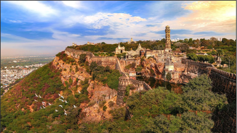
| The project utilises a rated head of 121.35 m and features an Upper Reservoir with a capacity of 1.9 TMC, created by a 6 km long, 32 m high Geomembrane Faced Rockfill Dam, which sources water from the existing 258.47 TMC Gandhi Sagar reservoir. The water conductor system, with a capacity of 1798.92 cumec includes an upper intake, eight penstocks/ pressure shafts measuring 7.5 m in diameter and approximately 559 m in length each, a tailrace outlet/ lower intake, and a tailrace tunnel/ channel. The pit powerhouse, situated at a depth of 80 m, houses seven units of 240 MW each, along with an additional two units of 240 MW each. A cofferdam within the Gandhi Sagar reservoir facilitated the construction of the pit powerhouse and lower intake. Lying within the Precambrian Vindhyan Super Group of sedimentaries, the Upper Reservoir lies over a plateau comprising sub-horizontally bedded quartzitic sandstone of Kaimur Group. The water conductor and powerhouse lie within shales of the underlying Semri Group. The NE-SW striking lineaments of regional persistence characterize the site and are represented by the presence of completely or highly weathered material referred as ‘murrum’. Considering preponderance of subvertical sets of joints, inclined drilling was preferred that helped define the engineering geological model. A stratum contour map defining the depth of sandstone-shale contact proved a ready reckoner in the ground appreciation and design of the upper reservoir. The plinth of the GFRD has been laid on sound rock and curtain grouting through inclined holes is underway. The cut slopes of the 80m deep pit powerhouse have been designed as flatter slopes of 1V:1.5H to 2V:1H in soil and weathered rock in the upper parts followed by steeper slopes of 6V:1H in fresh rock at depth. 8m long, 32mm dia grouted rock bolts at spacing 1.5m and 2.0m c/c with 150mm thick shotcrete with wiremesh have been installed for reinforcing the cut slopes. The coffer dam features a central impermeable barrier in the form of sheet piles that were placed in the dumped soft fill. Complementing the technical visit, delegates will embark on a cultural journey to Udaipur and Chittorgarh, where the grandeur of Rajput architecture and the heroic tales of warriors unfold. Udaipur, the “City of Lakes,” offers breathtaking palaces, while Chittorgarh narrates the saga of valor and resilience through its historic fort and monuments. The excursion has been arranged in collaboration with Greenko Group, the frontline developer of pumped storage projects in India. |
|
|

|